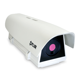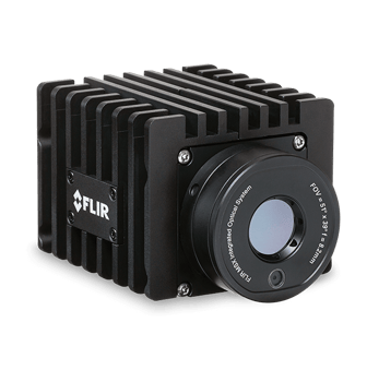
FLIR A65 IR Temperature Sensor
Brand :
Teledyne FLIR
Categories :
Fixed Thermal Cameras
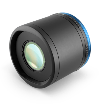
, Lense
The FLIR A65 is a thermal imaging temperature sensor for process control/quality assurance, fire prevention, and condition monitoring that offers comprehensive visual temperature monitoring. The A65 integrates seamlessly into existing systems and provides temperature linear output through GenICam™ compliant software.
Plug-and-Play
Easy setup thanks to GigE Vision and GenICam compliance and GigE Vision lockable connector.
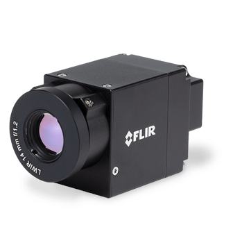
Affordable and Compact
At just 4.1 × 1.9 × 1.8 in, the A65 brings thermal imaging to your smallest spaces at an affordable price.
Connect Multiple Cameras
Synchronize between multiple cameras for greater coverage and communication, or for stereoscopic applications.
Specifications
-
EMC
EN 61000-6-2 (Immunity) EN 61000-6-3 (Emission) FCC 47 CFR Part 15 Class B (Emission)
-
Accuracy
±5°C (±9°F) or ±5% of reading
-
f-number
1.25
-
Digital Inputs
1× opto-isolated, "0" <1.2 VDC, "1" = 2–25 VDC.
-
Digital Outputs
1× opto-isolated, 2–40 VDC, max 185 mA
-
Image Frequency
30 Hz
-
Digital Output Purpose
General purpose output to ext. device (programmatically set)
-
Thermal Sensitivity/NETD
<0.05°C @ 30°C (86°F) / 50 mK
-
Digital I/O connector type
12-pole M12 connector (shared with Digital Synchronization and External power)
-
Ethernet
Control and image
-
Ethernet Type
Gigabit Ethernet
-
Digital Inputs
1× opto-isolated, "0" <1.2 VDC, "1" = 2–25 VDC.
-
Ethernet Power
Power over Ethernet, PoE IEEE 802.3af class 0 Power
-
Digital Outputs
1× opto-isolated, 2–40 VDC, max 185 mA
-
Ethernet Standard
IEEE 802.3 / RJ-45
-
Ethernet Protocols
TCP, UDP, ICMP, IGMP, DHCP, GigEVision
-
Synchronization in
1×, non-isolated
-
Synchronization out
1×, non-isolated
-
Digital input purpose
General Purpose
-
Digital Output Purpose
General purpose output to ext. device (programmatically set)
-
Ethernet Communication
GigE Vision ver. 1.2 Client API GenICam compliant
-
Ethernet Connector Type
RJ-45
-
Ethernet Image Streaming
8-bit monochrome @ 30 Hz Signal linear/ DDE Automatic/ Manual Flip H&V 14-bit 640 × 512 pixels @ 30 Hz Signal linear/ DDE Temperature linear GigE Vision and GenICam compatible
-
Synchronization in - type
LVC Buffer @3.3V, "0" <0.8 V, "1" >2.0 V.
-
Digital I/O connector type
12-pole M12 connector (shared with Digital Synchronization and External power)
-
Digital I/O supply voltage
2–40 VDC, max 200 mA
-
Synchronization Out - type
LVC Buffer @ 3.3V, "0"=24 MA max, "1"= –24 mA max.
-
Synchronization in - purpose
Frame sync in to control camera
-
Digital I/O isolation voltage
500 VRMS
-
Synchronization out - purpose
Frame sync out to control another Ax5 camera
-
Digital Synchronization Connector Type
12-pole M12 connector (shared with Digital I/O and External power)
-
Focus
Fixed
-
f-number
1.25
-
Focal Length
25 mm (0.98 in.)
-
Detector Type
Focal plane array (FPA), uncooled VOX microbolometer
-
IR Resolution
640 × 512 pixels
-
Detector Pitch
17 µm
-
Spectral Range
7.5–13 µm
-
Image Frequency
30 Hz
-
Field of view (FOV)
25° × 20° with 25 mm lens
-
FLIR Screen-EST Mode
No
-
Detector Time Constant
Typical 12 ms
-
Thermal Sensitivity/NETD
<0.05°C @ 30°C (86°F) / 50 mK
-
Spatial resolution (IFOV)
0.68 mrad
-
Accuracy
±5°C (±9°F) or ±5% of reading
-
Emissivity Correction
Variable from 0.5 to 1.0
-
Camera size (L x W x H)
107.8 × 49.6 × 46.6 mm (4.2 × 1.9 × 1.8 in.)
-
Measurement Corrections
Global object parameters
-
Object Temperature Range
-25°C to 135°C (-13 to 275°F) / –40°C to 550°C (-40 to 1022°F)
-
Optics Transmission Correction
Automatic, based on signals from internal sensors
-
Atmospheric transmission correction
Automatic, based on inputs for distance, atmospheric temperature and relative humidity
-
External Optics & Windows Correction
Automatic, based on input of optics/window transmission and temperature
-
Reflected apparent temperature correction
Automatic, based on input of reflected temperature
-
Weight
0.21 kg (0.46 lb.)
-
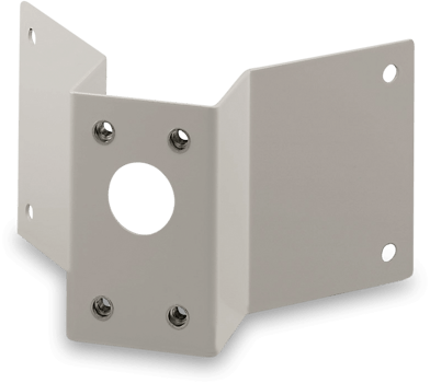
Base Mounting
4 × M3 thread mounting holes (bottom)
-
Housing material
Magnesium and aluminum
-
Package Includes
Cardboard box, thermal imaging camera with lens, focus adjustment tool, printed documentation, user documentation CD-ROM, FLIR Tools download card
-
EMC
EN 61000-6-2 (Immunity) EN 61000-6-3 (Emission) FCC 47 CFR Part 15 Class B (Emission)
-
Shock
25 g (IEC 60068-2-27)
-
Vibration
2 g (IEC 60068-2-6 & MIL-STD810G)
-
Encapsulation
IP 40 (IEC 60529) with base support mounted
-
Tripod Mounting
UNC ¼"-20 (on three sides)
-
Storage Temperature Range
–40°C to 70°C (–40°F to 158°F)
-
Operating Temperature Range
–15°C to 50°C (5°F to 122°F) The operating temperature range assumes that the camera is mounted on the base support (included in the package) or a similar type of heatsink.
-
Humidity (Operating and Storage)
IEC 60068-2-30/24 h 95% relative humidity 25°C to 40°C (77°F to 104°F)
-
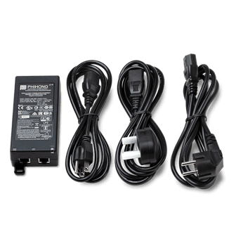
Voltage
Allowed range 10–30 VDC
-
External Power Operation
12/24 VDC, < 3.5 W nominal < 6.0 W absolute max
-
External Power Connector Type
12-pole M12 connector (shared with Digital I/O and Digital Synchronization )